The other guitarist/vocalist in Magpies plays through a Carvin VT50 50W Vintage Amp Head/Cab and uses the Carvin FS22 to switch channels on the amp. It’s a great, great sounding amp, but the footswitch does not have any indicators to show what is happening on the amp. So I wanted to write this post about modifying a Carvin FS22 to include LED indicators for any of you out there that are looking to do the same!
So let’s first talk about the FS22 foot pedal. It’s a dual-function foot pedal (controlling channel select and reverb/effects). This is done by connecting a TRS (Tip/Ring/Sleeve) Stereo cable into the back of the amp. The switch happens with tip to ground or sleeve to ground depending on what you’re wanting to switch.
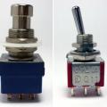
To add LEDs will require some parts. You’ll need to update the footswitches from SPDT to 2PDT. For this build, I did not have 2PDT footswitches on hand, and ended up using 3PDT footswitches. 2 LEDs with LED bezels and battery snap and battery clip. Rivets/rivet gun ideally for securing the battery clip. I also used 2x 2.2k limiting resistors for the LEDs since I had super bright LEDs on hand.
Once removing the small 4 screws on the end of the switch where the TRS cable comes, you can slide out the faceplate where the switches are connected. I always like to take a photo of original wiring (you know.. just in case).
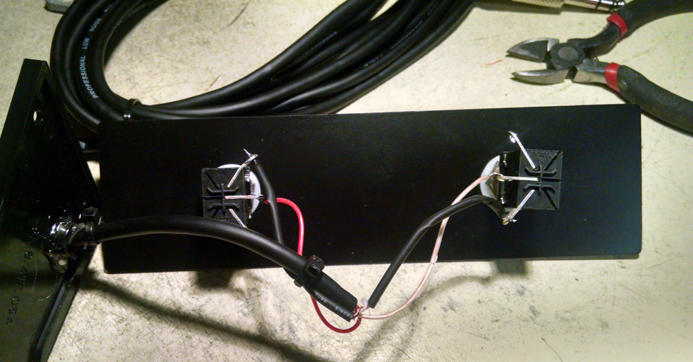 As you can see, the shield is split to either the top lug or the bottom lug. The Tip is attached to center on the left, and the Sleeve is attached to the center lug on the right. So, they’re basically opposite of each other (signal to ground). I went ahead and cut the leads from the lugs and removed the switches.
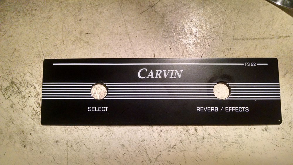 Flipping the faceplate over, we’ll need to add some drill holes. For this modification, I will need 2 LED holes above the footswitch and 2 small holes where I’ll use rivets to secure the batter clip to the underside of the faceplate.
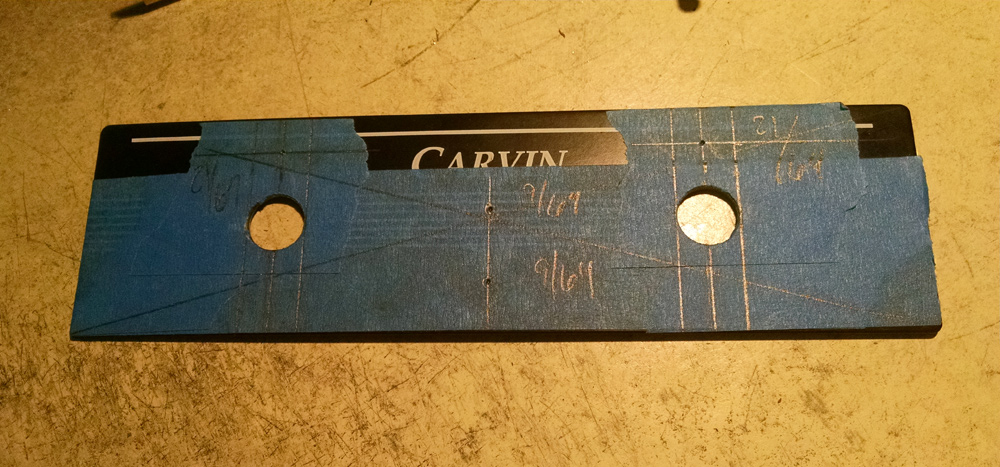 I like to use painters masking tape to start configuring my center points and determining where you want holes. I want the LED holes to be directly above the footswitch and the battery clip rivet holes to be in the center. Make sure you dry fit and ensure that the footswitch washers, bezels and the edge of the outer shell of the footswitch to cross each other. Measure 5 times.. drill once.. right?
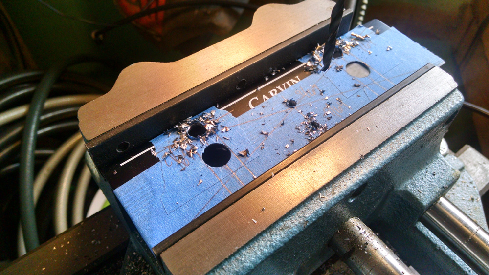 After center-punching your points, drill the faceplate. I would highly recommend a good vise and drill press. Don’t do this with a hand drill, etc. Now, I did run into a problem. The faceplate is made out of steel and not aluminum. Even with my drill press and vise, my bit wandered due to the hardness of the metal. I should have used a step bit since my bits flexed slightly.
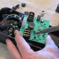
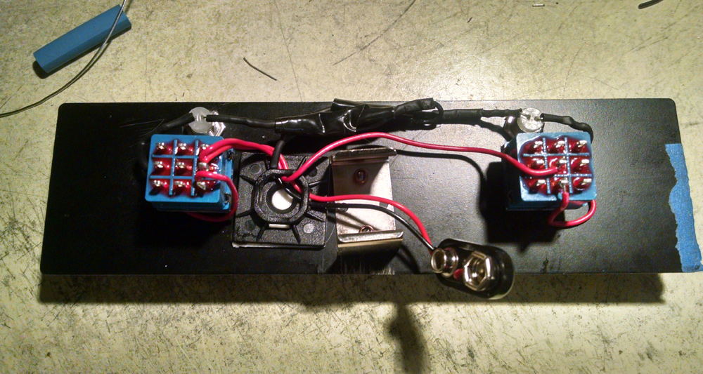 After the holes have been drilled, it’s time to add the new components. I added the pair of 3PDT switches, LEDs, bezels, limiting resistors, riveted the battery snap/clip and small adhesive mount to help secure the battery further. The wiring is pretty simple. Basically, we’re going to split the ground from the battery snap to the negative (cathode) lead on the LED. I also included the 2.2K resistor on the cathode side as well. The positive lead from the battery snap goes to center lug and that is also jumped to the other switch. Positive (anode) side of the LED is connected to the bottom lug. At this point, you’ll need to test. By attaching a battery, the footswitches should light on/off. If this does not work, you’ll need to debug.
The footswitch control has nothing to do with the LED portion, so make sure this works first before attaching TRS cable back to the circuit.
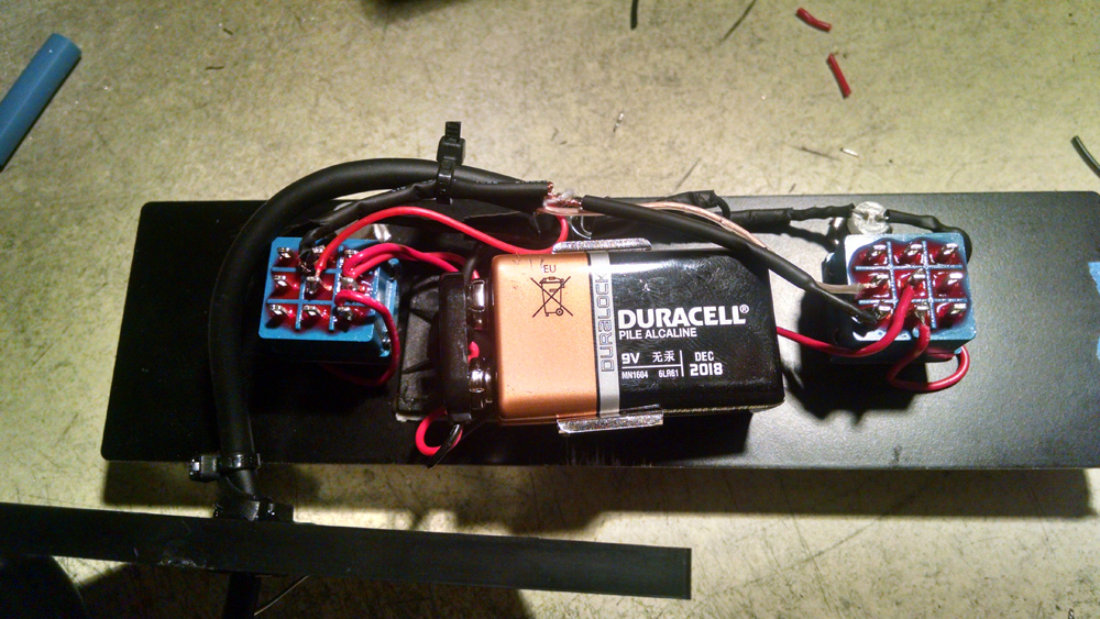 If the LEDs are lighting up, it’s time to add the TRS connections back. Since I’m using 3PDT, I’ll only be using 2 sets of poles. We’ll want to attach the ground to the top lug and the button lug on the two switches. Tip goes back to the center lug on the left, and the Sleeve to the center lug on the right (just like our original photo of the wiring)
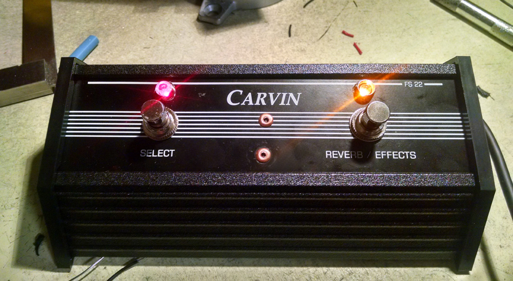 Now it’s time to button it all up and connect it to the amp. I used different LEDs (red and amber) for each side to help differentiate things further. The FS22 can be used across different Carvin amps, so functions, wiring *could* be different depending on the model of amp you’re using. The bottom line, pay attention to the original wiring – and follow that.
It’s been a little while since I posted a MIY (Mod It Yourself) post.. that was fun!
Let me know what you think by commenting below!

